J.P.'s Gear Review v2.0 - Ep. 15 - Ampeg Opto Comp, and an input pad mod
 |
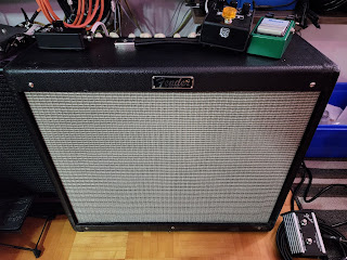
| A slightly modded Opto Comp... |
A bunch of things happened in the last few months, and most
of my hobbies got moved on the backburned while things stabilize. Now that
everything is quieter, I have more time to get back to writing and doing fun
stuff.
In this one, I’ll briefly discuss about the Ampeg Opto Comp
compressor pedal, and how you can mod it to externalize the 15dB pad jumper so
you don’t have to remove the backplate every time you need to change that
setting. Without further ado, let’s get to the review/mod thing.
What’s compression?
In a nutshell, when you compress a signal, you are changing its dynamic range by reducing the difference between the loudest and quietest parts of the signal. This is particularly useful when you are digging in your strings when playing: the transients showing up in the signal when the attack is stronger gets minimized and don’t blow out your VU meters (and your eardrums).
Compression is usually controlled by these parameters:
- Threshold: the incoming signal level (in dB) at which compression will start.
- Ratio: the amount of compression that happens once the level rises above the threshold. Standard compressors express ratios as X:1, where the signal will be attenuated to a level of 1dB above the threshold for every dB it crosses. E.g., in a 3:1 ratio, an input of 9dB above the threshold yields an output of only 3dB. Aggressive ratios of 9:1 and more are known as limiting.
- Attack time: amount of time the compressor will go from zero to full compression (according to the threshold and ratio).
- Release: amount of time it takes the compressor to stop compressing after the signal falls below the threshold.
Most compressors also have a “makeup gain” stage, or some
amplification of the compressed signal before it reaches the output. This will
make up for the lost volume by increasing the level of the output but will keep
the reduced dynamic range. This output gain stage is pretty much required to
get matching input and output volume levels.
There are many ways of achieving compression: VCA (voltage-controlled amplifier), optical,
FET, and Delta- μ (pronounced delta-mu). I will be giving a brief overview of optical compression, but if you are interested in a more detailed explanation of the different ways a signal can be compressed, iZotope by Native Instruments has a pretty good article on that.
Ampeg Opto Comp: what is it, and is it good?
Ampeg announced two new pedals at the 2018 Winter NAMM show:
The Opto Comp compressor and the Liquifier Chorus. They were both officially released
to market a few months later in April 2018. At 179$CAD at the time of writing
this article, it’s not that expensive and is an excellent entry in the
affordable-ish compressors.
The outside
The pedal is a nice, solid, custom-made white enclosure that
measures 56mm by 66mm by 114mm (or 2.2” by 2.6” by 4.5” for the
metric-impaired). It exposes three controls: Compression, Release, and Output
Level. It can be powered by a 9V battery or an external 9VDC power adapter that
can provide more than 25mA of current. It weighs about 300g (or 0.6lbs).
The controls
The compression can be set between 1:1 and 10:1, with 3:1 when
the knob is at the center position. Release time vary between 75ms and 600ms, but attack time is fixed at roughly 10 microseconds as with most optical compressors. The
output level can be set from mute to a +14dB boost, with unity gain roughly
at noon. The pedal also boasts two LEDs: a nice purple one to let you know the
effect is engaged, and a green one with varying brightness to indicate gain
reduction (LED brightness increases as gain reduction increases).
The fourth (and hidden – but advertised) setting is the 15dB
pad jumper. This allows you to switch between normal operation (with no volume
pad) and adding a 15dB pad to the input signal before it reaches the
compression circuitry. It’s particularly useful with active instrument that
usually have much louder outputs so their signal doesn’t hit the compressor that
much harder than that of passive instruments. Unfortunately, this jumper is
only accessible by removing the back cover and manually moving said jumper
between pins 1-2 (normal operation) and pins 2-3 (15dB pad). Why is it not a
simple toggle on the pedal? Only the designers know, but we’ll rectify that
later.
The pedal is true bypass so you get a satisfying clicky
footswitch to toggle the effect.
The tech
It uses an optical compression circuit
that relies on a light source and a photoresistor to tell the rest of the
circuitry how much compression to apply, and how fast to do it. The audio
signal at the input feeds a light source that shines on a photoresistor and the time
it takes for the light source and the light-sensitive resistor to react is what is controlling the compression. This delay, while fast, is
not instantaneous and that's what set optical compressors apart. Different types of lighting element (incandescent or LED,
for example) will illuminate at different speed, and the material the
photoresistor is made of will have an impact on how fast it will react to
light.
The attack and release of optical compression circuits are
not linear. Its initial release time will be faster the harder you hit the
circuit and its return to an uncompressed signal will curve. This
characteristic of optical compressors makes them more musical and smoother than
FET-based compressors, and it is also what makes them difficult to simulate
digitally.
Is it good?
Why yes, yes it is. Compression is one of those effects that
can be so subtle you’ll barely hear it, but you’ll 100% feel it. Optical compression
has a natural response that maintains clarity and smoothness at high
frequencies which makes it great for vocal and bass as the low-end will be
preserved.
Summary
Optical compressors are by far my favourites for the way they
operate and their low overall distortion. The Opto Comp has been on my board
since I purchased it August of 2021 and it’s here to stay. Its simple and easy
to understand controls make dialing in the perfect amount of compression an easy
task, and most of the time it’s an always-on “set and forget” pedal. The only
issue I have with it is the 15dB pad not being switchable from the outside. If
you want to try an optical compressor but don’t want to shell out 300$ for one,
the Ampeg Opto Comp is very good option.
The All-Important Rating™
Build quality: 9/10. It’s solid, well-made, and the
custom enclosure looks great. The potentiometers and jacks are solid stuff, the
PCB is neat and is screwed into the enclosure instead of being held in place by
the potentiometers, jacks, and switches. The pad jumper, though? It should have
been a standard-size jumper instead of a super-tiny one you need tweezers to
manipulate, or even better: a toggle switch.
Sound quality: 10/10. It sounds natural and smooth.
It’s perfect for bass.
Usability: 8/10. I have to dock two points for that
category just for the pad jumper situation. The accessible controls are clear, simple,
and well… accessible. The pad jumper should have been a switch on the main
cluster of controls (i.e., with the potentiometers) that you can access without
having to remove the backplate. Although it is usable in normal mode, you may
end up with too much compression.
Modability: Yes. We’re getting to that part.
Modding the Opto Comp
It is now time to discuss modding that 15dB pad
jumper to make it accessible from the outside. First, let’s see what we’re
dealing with:
 |
| The pin header is right beside one of the mounting screws. |
There are a few options we can consider:
- Add a TRS jack to the pedal that will be connected to a small remote-control box with a footswitch to toggle the input pad on or off.
- Adding a toggle switch protruding from the side of the pedal that we can flip on or off.
- Override the 15dB pad circuit to replace it with a potentiometer to control the level of the input signal.
Options one and two are the easiest to implement as we only
need to wire components to the existing pin header for the jumper. Option three
would require deeper analysis of the circuit to identify which resistor(s) are
in the pad circuit to remove them and wire the potentiometer in place, but I’m not
really interested in doing that. I want to retain the original circuit in place
and just exteriorize the jumper to be easily actionable.
Option one: adding a jack
My first idea was to go with a remote toggle that you can
plug in when needed and just press the footswitch to toggle it on or off. I made
some tests and removing the jumper entirely defaults to normal operation, which
is great. That way, the remote-control box doesn’t need to be connected for the
pedal to pass signal.
The wiring is simple. The pin header has three pins, and a
TRS jack has three pins. Tip goes to pin 1, ring goes to pin 2, and sleeve goes
to pin 3. Next step is to desolder the pin header and solder the wires to the
correct pins and verify continuity with a multimeter. I unfortunately did not
take picture of that.
Positioning the jack in the enclosure is the following step.
Considering the thickness on the jack and the free space in the enclosure, the
best location is on the output side where the foam battery support is, roughly
in line with the output jack with enough clearance so the jack does not touch
the PCB. This means that we will lose the foam battery support to make place
for the jack, but I’m fine with that since it is only used wired anyways. Make
sure you calculate clearance properly and that you also consider the screws
for the PCB mount when drilling the hole, otherwise you’ll need to re-drill it…
 |
| Yeah, it's a bit lopsided... |
Now that this is done, we can focus on the control box. We’ll need a small project box, an SPDT footswitch (3PDT is fine and much easier to obtain), and a ¼” jack. The wiring from the jack to the 3PDT footswitch is simple: Ring goes to the switch common, tip goes on side, and sleeve goes on the other. Verify continuity between jack and footswitch with a multimeter. Do the same with the jack’s ring (the common signal) and the tip and sleeve by flipping the switch to make sure the signal follows the correct path and is not broken. If you get no signal whatsoever and you are using a 3PDT switch, make sure the switch is wired in the correct orientation.
 |
| Small box for a small project, with just enough space for a footswitch and a jack. |
Now that we’ve done all the wiring and soldering, it would be the right time to discuss which type of ¼” jack to use. For this application, you’ll need an isolated jack, one that is not grounding the sleeve to the enclosure and where the barrel is most likely made in plastic. I figured that the hard way when I used the first two Neutrik TRS jacks I found in my stash and soldered them without thinking about it. As one would expect, whenever I’d toggle the 15dB pad, I’d get nothing because it would get grounded via the enclosure… Switching to plastic Amphenol jacks with properly isolated contacts solved the issue, but it did highlight a different problem.
This way of controlling the pad will introduce noise, and lots of it. When we think
about it, pin 2 of the jumper pad send the audio signal and we are transforming
that into a giant antenna by adding a who-knows-how-long external, ungrounded
cable in the equation. Sure, we could get TRRS jacks and a TRRS cable to shield the cabling, but that’s
getting expensive and ¼” TRRS components are not particularly easy to find. A 3.5mm
TRRS cable would look out-of-place, and I’d be worried about its durability.
After testing it out for an hour or two, having a jack and an external control
box would work, but not in that form and would require an investment I do not
want to make.
I do, however, have a nice toggle switch and I may have some
shielded cable in my stash of parts…
Option two: adding a toggle
With the failure of the remote-control box, let’s keep it
simple. Just a simple switch and a short length of wire from the pin header to
the switch itself. Let's also shield that small length of wire, for good measure.
The toggle switch I have that would fit the bill is
unfortunately slightly larger than the hole I drilled for the jack, so first
order of operation is to enlarge it with a step-bit to the proper size. The
clearance is good, and this brings the internals of the switch perhaps a
millimeter away from the output jack.
 |
| The slightly enlarged hole is almost covering the first, incorrectly positioned hole. |

The switch I’m using is an on-on switch that has two sets of two pins that gets shorted depending on the toggle’s position: 1-2 gets shorted in the top position, 3-4 gets shorted at the bottom position. The wiring will need to bring pin 2 of the pin header to both pin 1 and pin 3 of the switch, with pin 2 and 4 of the switch as the return wires to pin 1 and 3 of the pin header respectively. The shielding of the wire will need to go somewhere, and for that, a grounded support lug of the output level potentiometer will do just fine. Continuity has been verified between the different connection points and with the switch in both positions, and everything looks good.
 |
| I ran out of shrink tubing to isolate the exposed bit of shielding wire, so I used a bit of the 4-conductor cable sleeve instead. |
 |
| Again, no shrink tubing to isolate the exposed part of shielding, but this part of the PCB does not have any circuit elements to short with. Note that the shielding is only soldered at one point, otherwise you end up with a ground loop. |
With the soldering complete, we can reinstall the PCB inside the enclosure and test our handywork. This solution is a lot simpler and is what I should have done instead of going the fancy way. More importantly, it works. We can now toggle the input padding at will without removing the backplate!
 |
| Completed project! |
Post-mortem of this little modding project
Too much time was spent designing a fancy solution to a
problem that did not require that level of complexity. It worked (once the correct,
non-grounding jacks were installed), but to get it fully working, more
expensive parts would have been needed and they’re not easy to find. Even Mouser
and DigiKey do not have ¼” TRRS connectors in stock!
The simplest solution to add a toggle switch and some shielded cable is much better, and I should have done that from the get-go. It requires much less time and parts and it just works with no added noise.
10/10, would definitely mod again.

Comments
Post a Comment