Posts

Showing posts from June, 2022

Transistor update! - AionFX Phobos Germanium Fuzz

Image
  In my previous post , I mentioned waiting on some nice Telefunken transistors. They finally arrived after being in transit for only 10 days (and I am still waiting for some PCBs from the US that were shipped on the 5th of June...) ! The original transistors The transistors included in the kit were two Russian transistors (one MP16B and one MP21A), and a Tungsram AC125. They are relatively cheap and easy to find, and they perform admirably.  Their hFE value were 62, 56, and somewhere around 90, respectively. These values are perfectly suited for the Tone Bender circuit. Don't get me wrong: they sound great and the fuzz they generate is very clean, but I want a fuzz that is a little dirtier. I found a good article from Coda Effect where he built an earlier revision of the same PCB I have, and he used AC116 transistors. By some sheer luck, I managed to find the exact same transistors on eBay for about 20$, shipping included. What could go wrong? The "new" transistors Thei

JP's Gear Review v2.0 - Ep. 1 - AionFX Phobos Germanium Fuzz

Image
As I mentioned in a previous post, I purchased an AionFX Phobos kit . I received it earlier this week, but I was still waiting on some extra parts. Since the Telefunken AC116 transistors I ordered are most likely coming in from Germany by crossing the Atlantic on a dinghy, I went ahead and used the transistors included in the kit.  The parts The parts came neatly packaged in different bags. The kit came very well packaged, and arrived in about one week from the US. The quality of the every part is top-notch. PCB The PCB is really well designed. It's a simple 2-layers PCB, red in color. The kit includes two PCBs: the Tone Bender circuit itself with a breakaway part for the 3PDT switch a small board to host the DC jack and input/output jacks Each board is designed to use 3-strands and 4-strands wire assemblies (with the appropriate headers included) to connect to each other. This minimizes the spaghetti-wiring potential. I have only two small issues with the PCBs: The spacing between

Overdrive, distortion, fuzz, hard clipping, soft clipping... What gives?

Image
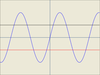
 When talking about distortion, I often hear questions about what difference there is between an overdrive, a fuzz, and a distortion, and what's different between soft and hard clipping. I'll attempt to briefly answer those questions in the post.  What's clipping? "Clipping" is what happens to a signal when it is too powerful (or too hot) for a device. The type of clipping that is done depends on the circuit. In a effect pedal where an oversaturated signal is the intended end-result, makers will place certain diodes to clip the negative and positive parts of the waveform. The diodes don't have to be identical; you can use different diodes on both paths and-or combine many different diodes in series to shape the clipping to what you need. Designs using identical diodes are called symmetrical clipping circuits, and designs using different diodes are called (wait for it) asymmetrical clipping circuits. Reference signal The following graphs all use the following r

The Tone Bender circuit

Image
A few weeks ago, I ordered a few parts from Tayda Electronics for an unrelated project and stumbled on their Tone Bender clone PCB. From what I could see, it's most likely a Mark II or a modified Mark III with no tone circuit. Sadly, that shipment got lost in transit and they had run out of stock of that particular PCB, so I couldn't get a replacement. Their instructions set provides a diagram of the circuit, and it's a relatively simple one. I decided to try my luck, breadboard one and then solder it on a protoboard I have. First attempt I pulled out my breadboards, my spare parts, printed the diagram, and started my adventure. One thing to note on this circuit is that like most early effect circuits, it is built around a positive ground rail. It means you cannot power these pedals with a daisy-chain power supply otherwise you'll introduce noise on your signal chain (and we don't want that). One way to work around that is to build a charge pump to invert and clean