3PDT footswitch and true bypass wiring
Whenever I assemble a new effect pedal, I always end up confused about the wiring required for the 3PDT footswitch. More often than not, the wiring is the same, but presented differently or in a confusing manner in the assembly instructions of the different kits/PCBs and I always end up having to draw it out.
As well as the wiring, there's some theory about switches. You can go directly to the wiring diagram and explanations by clicking this link.
What are switches, really?
Let's first start with the humble on-off switch:

SPST (single pole, single throw) switches have only one pole, and only one throw (or circuit that can be closed). When the switch is open there's no signal going anywhere. When it's closed, the signal goes through. It's your basic on/off toggle.
Let's complicate things a bit more by introducing... a second throw:

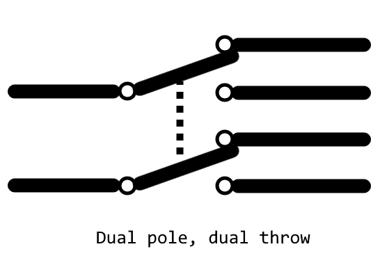
From these two basic switches, more complex switches can be made by adding poles:

DPST (dual pole, single throw) and DPDT (dual pole, double throw) use the same principles as the single pole switches. Poles may or may not be toggled at the same time, depending on the type of switch. Poles that are always synchronized are shown with a dotted line linking them.

The 3PDT is a three pole, dual throw switch:

 The switch has 3 columns and 3 rows. Notice the orientation of the pins: they are flat, and rectangular. The longer side should be parallel to you (i.e., go from left to right when you look at it).

 I used a 3PDT as a toggle switch for a gain stage in ½-watt amp-in-stompbox build (with it's own LED with the +9V wired to the right center pin and the LED on the top-right pin).

The number of available pins on a switch is equal to the number of poles and throws for each poles. SPST switches has 2 pins, SPDT has 3, DPST has 4, DPDT has 6, 3PDT has 9, etc.
On-off, on-on, on-off-on, on-on-on, latching, momentary... Which one to choose?
Switches with multiple poles and-or throws can be of various type. Usually, you will find switches with two or three states. The one you need depends on your circuit.
In effect pedals, the footswitches are "latching", and "on-on". The footswitch will retain its position (latching), and the signal will go through on both states of the footswitch. Momentary footswitches are often used for tap-tempo applications and will usually be SPST.
How do you wire a 3PDT?
The wiring of a 3PDT footswitch in true bypass circuits is, 99.99% of the times, identical in every effect pedal. The layout of the switch is as follows:

The center row is your common pins. These will be connected to either the top or bottom row when toggling the footswitch.
Wiring it up is quite single, but it can be confusing at first:

- The first two pins of the top row are going to be linked together. This will take you dry signal from the input jack are wire it directly to the output jack to bypass the PCB/circuit entirely. The last pin will stay not connected.
- The center row are your common pins:
- Left pin comes from the input jack
- Center pin goes to the output jack
- Right pin goes to the LED and its series resistor
- The resistor is important if you do not want to blow up the LEDs. For a 3V LED, a 270-390 ohms resistor should be enough depending on the color. You can use a higher resistance to control the intensity of the LED.
- AllAboutCircuits has a nice calculator to help you with that: https://www.allaboutcircuits.com/tools/led-resistor-calculator/
- The bottom row are going to/from the PCB:
- Left pin goes to the PCB/circuit input
- Center pin comes from the PCB/circuit output
- Right pin comes from the +9V of either the DC jack or PCB/circuit
If you want to have a different LED lighting up for each state, connect the +9V from the DC jack or PCB to the center right pin, one resistor to the top-right pin, and a different resistor to the bottom-right pin. Make sure you have the proper series resistances to not burn the LEDs.
If you need to use a 3PDT as a simple on-off switch, simply connect it like this:


Comments
Post a Comment