JP's Gear Review v2.0 - Ep. 2 - One knob fuzz: Analysis, build, and review
(Editor's note: It originally wasn't supposed to be a gear review, but here we are...)
Circuit analysis
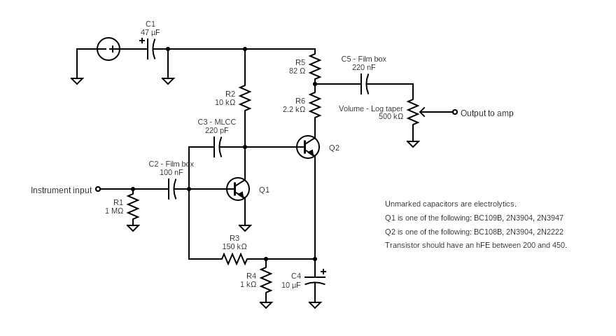
It is an extremely simple circuit. The transistors have a fixed bias, and there's no fuzz control. It's always on, and always maxed out (as it should be). There's no tone stack and no frequency filtering either. It was designed as a silicon fuzz, and the original schematics calls for BC109B and BC108B transistors. Since they can be difficult to find and expensive to acquire, functional equivalents can be used instead. I like 2N3904 since they are cheap and works just as well as the original transistors. All in all, it's a silicon Fuzz Face that uses NPN transistors and for which the Fuzz knob has been removed. The schematics for both are almost identical.
The schematic above is the one I used for both iterations I made.
Power from the positive rail (+9V) first goes through a filter cap to remove any parasitic AC current, before going to the collector of Q1 through a 10㏀ resistor to drop the input voltage to 1.9V. Q1's emitter goes to ground. Instrument input signal is attenuated through a 1㏁ resistor before going through a coupling capacitor. It is then split in three branches: to the base of Q1, to another coupling capacitor linking to the collector of Q1 and the base of Q2, and to ground through a 150㏀ resistor, a 1㏀ resistor, and a 10µf capacitor.
Now that we have the signal amplified once and sent to the base of Q2, its collector is connected to the positive rail through a voltage divider that lowers the voltage to about 6.5V. The other side of the voltage divider goes through a coupling capacitor to filter out the DC (from the positive rail) from the output of Q2 and finally to the volume potentiometer. The emitter of Q2 goes to ground through the same 1㏀ resistor and 10µf capacitor as the instrument input branched before the base of Q1.
The transistors are in a multistage amplifier configuration (or cascading amplifier) where the output of one transistor is connected to the base of the transistor of the next stage. In this schematic, they are daisy-chained horizontally. It is the easiest and most common way to chain transistors together, and it effective enough for our purposes.
The build
This build is probably one of the cheapest you can do. You'll need about 15 to 20$ worth of parts, depending on where you get the enclosure. Here's the BOM for this build:
| Code | Description |
|---|---|
| C1 | 47µf, electrolytic |
| C2 | 100nf, film box |
| C3 | 220pf, MLCC |
| C4 | 10µf, electrolytic |
| C5 | 220nf, film box |
| Q1 | BC109B (NPN). Alternatively 2N3947 or 2N3904 can be used. |
| Q1 | BC108B (NPN). Alternatively, 2N2222 or 2N3904 can be used. |
| R1 | 1㏁, ¼W, 1% tolerance, metal film |
| R2 | 10㏀, ¼W, 1% tolerance, metal film |
| R3 | 150㏀, ¼W, 1% tolerance, metal film |
| R4 | 1㏀, ¼W, 1% tolerance, metal film |
| R5 | 82Ω (100Ω or 150Ω should also work fine), ¼W, 1% tolerance, metal film |
| R6 | 2.2㏀, ¼W, 1% tolerance, metal film |
| Other | PCB/stripboard/Veroboard/protoboard to assemble the circuit on |
| Other | 3PDT footswitch |
| Other | 2x Rean Neutrik NYS229 mono jack (or NYS230 stereo jack), open back |
| Other | 2.1mm DC power jack |
| Other | 5mm LED with bezel |
| Other | Current limiting resistor for LED (1.8㏀ is a good value to start with; like the other it should be ¼W, 1% tolerance, metal film) |
| Other | Alpha 500k potentiometer, audio (logarithmic) taper, right angle leads, 16mm, 6.35mm shaft diameter |
| Other | Ridiculously large potentiometer knob, for 6.35mm shaft diameter pots |
| Other | Hammond 1590B-style enclosure (125B is also a good option) |
| Other | 24AWG wire |
| Other | Optional: one of these 3PDT helper PCBs so you don't have to fight with the 3PDT wiring. You can buy them from GuitarPCB. |
For the electrolytic capacitors, I'd recommend that you stay with the "on"s: Nichicon, Lelon, Rubycon, Panasonic. Wurth Elektronik are also pretty good. In this particular build, I used JRB capacitors since it's what I had on hand. For film box, I use WIMA or Kemet. In a pinch, the cheap Tayda Electronics house-brand are usually good enough. For MLCC capacitors and resistors, I use whatever I can find. As long as the tolerances are tight enough you should not have any problems. Rule of thumb: pick parts with the tightest tolerance you can find, as long as it's not too expensive. If there's a 5-cents difference between 10% and 5% tolerance, it usually is a good investment to go with the 5%.
Before going straight to soldering the thing, test it out on a breadboard. It's much easier to figure out if something is misconnected.
 |
| V1 on the breadboard. |
Use your cheaper parts too, in case you release the Magic Smoke™ from some of them...
 |
| It's dead, Jim. |
I made 2 versions of this circuit. My first attempt didn't turn out so great for multiple reasons, but it works. The second one was mostly to have one that looks a tad better. In the below picture, V1 is on the right, and V2 on the left.
 |
| Yes, I know. I assembled V1 on the wrong side of the PCB. |
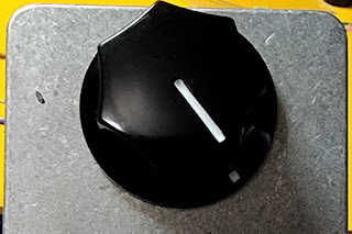
V2 is the one I put in the enclosure. Wiring is the same as 99% of other pedals out there, and it's even easier if you use a 3PDT helper PCB. As you can see, it's a pretty simple enclosure with only the LED, footswitch, and the single, ridiculously large knob on it:
The one-knob fuzz is a fun little circuit to build and experiment with. You can install sockets for the transistors and play around with different combinations (as long as the transistors you use are NPN). It's easy to build, and the parts are cheap. This circuit is simple enough that it can be integrated to anything that needs an on-off dirt switch. You could even make the pedal build simpler by removing the footswitch and LED, and having it always-on!
The All-Important Rating™
Build quality: 15/10 (but it's dependent on your builder skills)
Complexity: Beginner. It's a good introduction to transistor-based amplifier circuits and, if you assemble it from scratch, a good way to get into custom PCB wiring.
Effect quality: 10/10 (It's a fuzz, and it sounds great.)
Ease of use: Yes. (There's only one knob.)
Complexity: Beginner. It's a good introduction to transistor-based amplifier circuits and, if you assemble it from scratch, a good way to get into custom PCB wiring.
Effect quality: 10/10 (It's a fuzz, and it sounds great.)
Ease of use: Yes. (There's only one knob.)


Comments
Post a Comment